
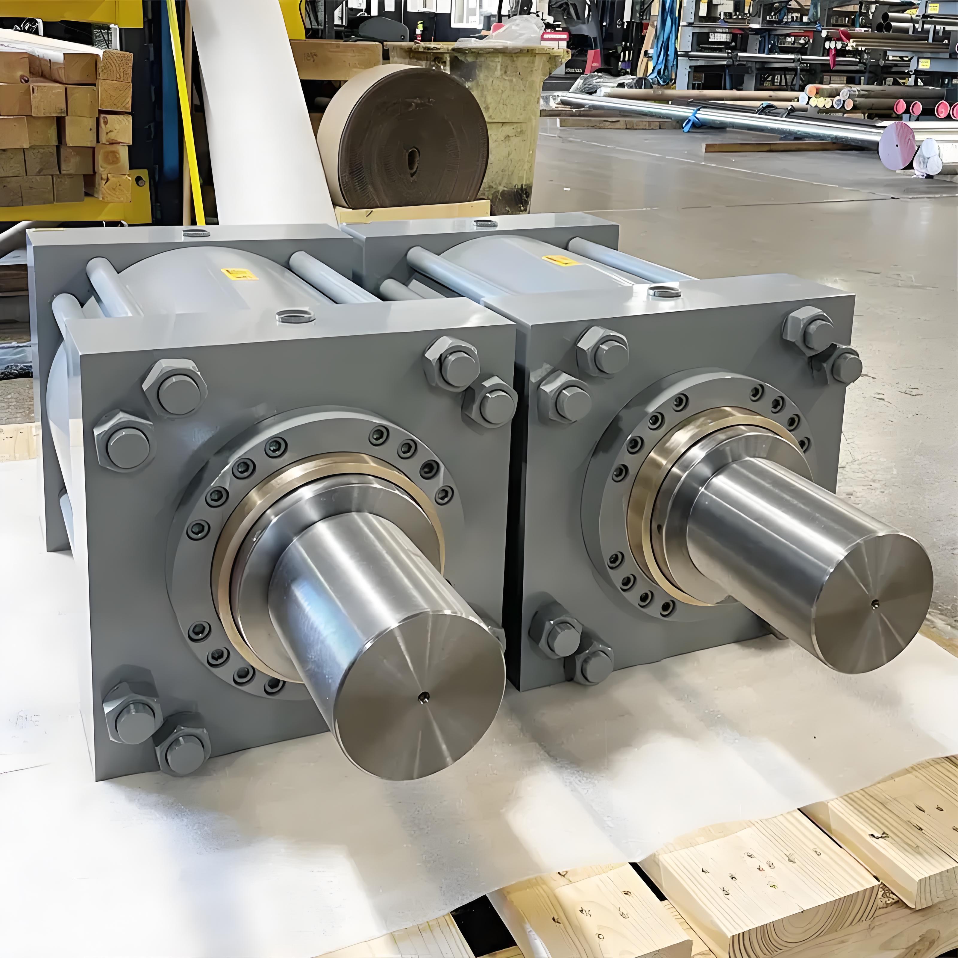
 Disassembly a tie rod cylinder
Hydraulic cylinder components play a vital role in every hydraulic system. Key parts include the barrel, piston, piston rod, head, base, seals, gland, ports, mounting points, and clevis. Each part supports the cylinder’s function, from pressure retention to motion transfer. When operators understand these elements, they can:
Perform targeted preventive maintenance, such as fluid checks and leak inspections.
Reduce downtime by identifying issues early and scheduling repairs.
Extend service life by maintaining smooth surfaces and proper lubrication.
Lower repair costs through regular cleaning, inspections, and protective coatings.
Key Takeaways
Hydraulic cylinders consist of key parts like the barrel, piston, piston rod, seals, head, base, ports, and mounting points, each vital for proper function and pressure control.
Choosing the right materials, such as steel alloys or corrosion-resistant metals, improves durability and performance based on the operating environment.
Regular maintenance, including fluid checks, seal inspections, and cleaning, extends cylinder life and prevents costly repairs.
Different cylinder types—tie-rod, welded, telescopic, and ram-style—serve specific applications and pressure needs; selecting the right type ensures efficiency and reliability.
Seals and glands prevent leaks and contamination; using proper seal materials and timely replacements keeps cylinders running smoothly.
Mounting options like flange, clevis, and trunnion affect cylinder stability and movement; matching the mount to the application reduces wear and improves safety.
Single-acting cylinders provide force in one direction, while double-acting cylinders control motion both ways; choosing the correct type fits the task requirements.
Understanding wear factors such as contamination, misalignment, and high pressure helps operators prevent damage and maintain optimal cylinder performance.
Main Hydraulic Cylinder Components

Barrel
Function
The barrel forms the main body of a hydraulic cylinder. It houses the piston and hydraulic fluid, providing a sealed environment for pressure to build and transfer force. The barrel must withstand high internal pressures and maintain precise internal dimensions to ensure smooth piston movement. Its structural integrity directly impacts the performance and safety of hydraulic cylinder components.
Materials
Manufacturers select barrel materials based on strength, corrosion resistance, weight, and cost. The following table compares common materials and their properties:
Material Type | Description & Properties | Advantages | Disadvantages / Notes |
|---|---|---|---|
Low Alloy Steel | Alloyed for improved wear, corrosion, abrasion resistance | Affordable, durable | No major drawbacks |
Nickel-Chromium Alloys | High tensile strength, corrosion resistant, good machinability and weldability | High strength, corrosion resistance | Higher cost |
Low Carbon Steel | Malleable, durable in oil and fuel, easily available | Cheap, durable | Yields easily, limited in acidic environments |
Stainless Steel 304 | Corrosion resistant, durable in acidic environments | Excellent corrosion resistance | Higher cost |
Titanium Alloy Grade 1 | Strong, lightweight, easy to machine, corrosion resistant | Lightweight, strong | Expensive |
Cast Iron Grade 60-44-18 | Ductile, strong load bearing, good surface finish | Low cost, good strength | Rust prone, difficult to weld, limited in acidic env. |
Lightweight, good strength, reduces system power demand | Lightweight, reduces environmental impact | Higher cost, less wear resistant | |
Composites (CFRP) | High strength-to-weight ratio, corrosion and fatigue resistant | Extremely lightweight, corrosion resistant | Very expensive, manufacturing complexity |
Plastics (POM, PA, PP) | Adequate strength, good vibration damping, chemical resistance | Lightweight, noise reduction | Limited strength, some absorb water |
Note: Surface treatments like chrome plating or carburizing further enhance wear resistance and durability, especially for steel barrels.
Maintenance
Proper maintenance extends the lifespan of the barrel and other hydraulic cylinder components. Under standard operating conditions, a well-built and maintained barrel can last twenty years or more. Regular inspection for wear, corrosion, and internal scoring is essential. Operators should use high-quality filtration to prevent contamination and avoid side loads that can cause barrel deformation. If wear occurs, refurbishing methods such as chrome plating can restore the barrel’s surface. With diligent care, the barrel often lasts the lifetime of the machine.
Piston
Function
The piston divides the internal space of the barrel into two chambers. It converts hydraulic pressure into linear motion, transferring force to the piston rod. The piston’s fit and sealing ability are critical for efficient operation, as they prevent fluid from bypassing and maintain pressure differentials.
Types
Pistons come in several designs, each suited to specific applications:
Single-Acting Pistons: Use hydraulic pressure to move in one direction. Retraction relies on gravity or an external force. These pistons offer simplicity and lower cost but only provide force in one direction.
Double-Acting Pistons: Hydraulic pressure acts on both sides, enabling push and pull actions. This design allows for better control and is ideal for repetitive or complex motions.
Tie-Rod Cylinder Pistons: Found in cylinders with threaded rods holding end caps. These pistons are easy to assemble and maintain, suitable for medium to light-duty tasks.
Welded Cylinder Pistons: Used in cylinders with welded end caps. They provide a compact, rugged design for high-pressure or harsh environments.
Telescopic Pistons: Consist of multiple nested stages, allowing long strokes from a compact cylinder. Common in dump trucks and agricultural equipment.
Ram Pistons: Feature a large diameter rod acting as the piston. This design simplifies construction and reduces cost, but requires careful guidance for horizontal use.
Materials
Pistons are typically made from high-strength steel or ductile iron for durability and wear resistance. In some cases, manufacturers use lightweight alloys or composites to reduce weight and improve efficiency. The choice of material affects the piston’s ability to withstand pressure, resist corrosion, and maintain a tight seal within the barrel.
Piston Rod
Function
The piston rod connects the piston to the external mechanism, transmitting the generated force to the machine’s moving parts. It must resist bending, buckling, and surface damage during operation. The rod’s straightness and surface finish are crucial for seal integrity and smooth movement.
Coatings
Manufacturers apply specialized coatings to piston rods to enhance corrosion and wear resistance. The most common options include:
Hard Chrome Plating: Adds a hard, wear-resistant layer that protects against corrosion, abrasion, and surface damage. Microcracks in the chrome retain lubricants, reducing friction and wear.
Thin Dense Chrome Plating: Forms a thin, dense chromium layer that significantly improves corrosion and wear resistance.
Global Shield Coating: An advanced, environmentally friendly coating that offers superior corrosion resistance and impact toughness compared to traditional chrome.
These coatings create protective barriers against oxidation, chemicals, salt water, and acids. They also provide a low-friction, high-hardness surface that extends the rod’s service life. Technicians can strip and reapply these coatings during maintenance without damaging the base metal.
Care
Proper care of the piston rod is essential for the reliability of hydraulic cylinder components. Physical damage such as scratches, corrosion, or wear can degrade seals and internal parts. Contaminated hydraulic fluid introduces particulates that scratch surfaces and accelerate wear. Corrosion from environmental exposure leads to rust and pitting, which damage seals when the rod retracts. Side loading due to improper installation causes uneven wear and shortens rod life. Regular inspection, correct installation, and use of appropriate seals and fluids help prevent these issues. Neglecting rod care often results in seal leakage, pressure loss, and ultimately, complete hydraulic cylinder failure.
Head and Base
Function
The head and base form the two end closures of a hydraulic cylinder. The head, also called the gland or front cover, supports the piston rod and houses the rod seal. The base, or cap, closes the opposite end and often serves as a mounting point. Both parts maintain internal pressure and keep hydraulic fluid contained. They also provide structural support, ensuring the cylinder withstands operational forces without deformation.
Types
Designers select head and base types based on cylinder construction and application requirements. The two most common designs are tie-rod and welded (mill-type) cylinders. The table below compares their features:
Feature | Tie-Rod Cylinders | Welded (Mill-Type) Cylinders |
|---|---|---|
Construction | Use high-strength threaded steel tie rods on the outside of the cylinder housing | Barrel welded or bolted directly to end caps; no tie rods needed |
Maximum Operating Pressure | Typically up to 3,000 psi | Designed for 5,000 psi or greater |
Typical Applications | General industrial (e.g., plastics machinery, machine tools) | Rugged environments (e.g., presses, steel mills, offshore) |
Regional Usage | Common in the U.S. | Preferred by European manufacturers for most industrial uses |
Cost | Less expensive due to simpler design | More expensive due to heavy-duty construction |
Material Considerations | Medium-grade carbon steel for heads and bases; stronger materials used for tougher tasks | Same materials but integrated end caps require robust welding |
Temperature Suitability | Standard carbon steels suitable for -5 to 200°F; may require alternatives in extreme cold | Same considerations apply |
Note: Welded cylinders offer higher pressure ratings and better durability for harsh environments, while tie-rod cylinders provide easier maintenance and lower cost.
Seals and Gland
Types of Seals
Seals play a critical role in hydraulic cylinder components by preventing fluid leakage and protecting internal parts from contaminants. The main types of seals include piston seals, rod seals, buffer seals, wiper seals, and guide rings. The table below summarizes their functions and material influences:
Seal Type | Function in Leakage Prevention and Performance | Material Influence on Seal Effectiveness and Leakage Control |
|---|---|---|
Piston Seals | Prevent lubricant and gas leakage; maintain pressure for efficient piston movement | Rubber and PTFE provide flexibility and durability, reducing leakage |
Rod & Buffer Seals | Rod seals keep pressure in and contaminants out; buffer seals cushion shocks and protect rod seals | Material flexibility and abrasion resistance extend seal life and reduce leakage |
Wiper Seals | Remove dirt and contaminants from rod surface; prevent ingress of particles and fluids | Materials like polyurethane and thermoplastic elastomers resist wear and maintain sealing efficiency |
Guide Rings | Absorb side loads; prevent metal-to-metal contact; protect seals from wear | Material strength and lubrication reduce wear and leakage |
Material selection for seals includes rubber (NBR, FKM, HNBR) for flexibility and oil resistance, PTFE for durability and low friction, and thermoplastic elastomers for abrasion resistance. Each material offers unique benefits for specific operating conditions.
Gland Role
The gland, sometimes called the rod gland or gland nut, holds the rod seals and wiper in place within the cylinder head. It guides the piston rod and ensures proper alignment as the rod moves in and out. The gland also allows for easy replacement of seals during maintenance. In some designs, the gland can be removed without disassembling the entire cylinder, reducing downtime and simplifying repairs.
Troubleshooting
Seal failure remains a common issue in hydraulic cylinder components. The most frequent causes include:
Hardening from high temperatures, leading to cracks and loss of elasticity.
Wear due to insufficient lubrication or excessive lateral load.
Scarring from improper installation tools or processes.
Fractures resulting from pressure spikes, backpressure, or poor materials.
Improper installation causing contamination or incorrect sizing.
Contamination by dirt, mud, or other particles that degrade sealing.
Chemical erosion from corrosive fluids or incompatible seal materials.
Tip: Regular inspection and timely replacement of seals help prevent leaks and maintain cylinder performance. Always use compatible fluids and proper installation techniques to extend seal life.
Ports
Types
Ports serve as the entry and exit points for hydraulic fluid in the cylinder. The most common port types include:
NPT (National Pipe Thread): Tapered threads, widely used in North America.
BSP (British Standard Pipe): Parallel or tapered threads, common in Europe and Asia.
SAE (Society of Automotive Engineers): Straight threads with O-ring sealing, popular in high-pressure applications.
Metric: Used in international equipment, offering compatibility with global standards.
Each port type must match the system’s plumbing and pressure requirements to ensure leak-free operation.
Placement
Engineers position ports to optimize fluid flow and cylinder performance. Typical placements include the head, base, or side of the cylinder. Proper port placement reduces turbulence, improves efficiency, and simplifies hose routing. In double-acting cylinders, ports appear at both ends to allow fluid to enter and exit each chamber. In single-acting cylinders, a single port usually suffices.
Note: Incorrect port placement can cause uneven pressure distribution, reduced efficiency, or even component failure. Always follow manufacturer guidelines for port selection and location.
Mounting Points and Clevis
Mounting Options
Mounting points serve as the critical interface between hydraulic cylinder components and the machinery they operate. Engineers select mounting options based on the required movement, load direction, and installation environment. The most widely used mounting options in industrial machinery include:
Flange Mounts: These rigid mounts feature a plate welded to the cylinder and bolted to a mating plate on the machine. Flange mounts provide a stationary, fixed centerline and offer high column strength. They do not allow rotational motion, making them ideal for applications where precise alignment is essential.
Trunnion Mounts: Pins positioned on each side of the cylinder barrel enable radial rotation in one plane. Trunnion mounts allow the cylinder to pivot, accommodating changes in load direction. Engineers can place these pins anywhere along the barrel to suit specific installation needs.
Clevis Mounts: U-shaped mounts welded to the barrel or rod end engage with a single tab and secure with a pin. Clevis mounts allow angular movement and are especially common where pivoting motion is required.
Cross Tube Mounts: Tubes welded across the barrel or rod end fit between two lugs and secure with a pin. These mounts often include bushings to absorb wear and provide smooth operation.
Lug Mounts: Single lugs welded to the barrel or rod end are machined and drilled for tight tolerances. Lug mounts can incorporate bushings or spherical bearings to improve alignment and reduce wear.
Custom mounting options exist to optimize fit, function, service life, and ease of assembly. Many hydraulic cylinder components follow NFPA and ISO standards, ensuring modularity and interchangeability. Common standard types include MP1 (fixed clevis), MP2 (detachable clevis), MF1 (front flange), MF2 (rear flange), MS2 (side lug), and MT1 (front trunnion). These standards help streamline maintenance and replacement in high-end hydraulic machinery.
Tip: Selecting the correct mounting option improves cylinder performance, reduces wear, and extends service life. Always match the mounting style to the application’s motion and load requirements.
Clevis Use
The clevis stands out as one of the most versatile mounting solutions for hydraulic cylinder components. Its U-shaped or forked end connects to a mating tab using a pivot pin, which allows angular motion and accommodates small misalignments caused by load shifts or machinery movement. This flexibility reduces strain on the cylinder, helping to extend operational life.
Clevis mounts maintain alignment, which is critical for precise movement and consistent force application. Proper alignment enhances operational efficiency and minimizes uneven wear. The clevis design also provides a cushioning effect at the end of the stroke, which helps absorb shock loads and protects both the cylinder and the machine.
However, clevis mounts are less rigid than flange mounts and may not handle high axial loads directly. Their design excels in applications where angular movement and alignment flexibility are more important than maximum rigidity. Stress concentration at the clevis pin hole and connection areas requires careful management to avoid fatigue and failure. Proper installation, including correct sizing and securing of the pivot pin, prevents excess play or misalignment that could lead to premature wear.
Note: Regular inspection of the clevis and pivot pin ensures safe operation and prevents unexpected downtime. Always follow manufacturer guidelines for installation and maintenance.
Cylinder Types

 tie rod hydraulic cylinder different mount type
Tie-Rod
Tie-rod hydraulic cylinders stand out for their modular construction and straightforward maintenance. Engineers design these cylinders with high-strength steel rods running parallel to the barrel. These rods secure the end caps, ensuring structural integrity and precise alignment. The compact design fits well in space-limited environments.
Key characteristics of tie-rod cylinders include:
Cost-effectiveness due to simple construction.
Modularity, which allows for easy customization and part interchangeability.
Straightforward maintenance, as users can disassemble and reassemble them with common tools.
Reliable performance, with the ability to generate high forces and operate at elevated pressures.
Use of high-quality seals for long-lasting operation.
Industries such as construction, manufacturing, agriculture, and material handling rely heavily on tie-rod cylinders. Common applications include forklifts, cranes, conveyors, pressing and forming machinery, tractors, harvesters, irrigation systems, excavators, loaders, and bulldozers.
Tip: Tie-rod cylinders follow NFPA standards, making them easy to replace or upgrade in many industrial systems.
Welded
Welded hydraulic cylinders offer a robust solution for demanding applications. Manufacturers weld the end caps directly to the barrel, eliminating the need for external tie rods. This construction results in a compact, durable cylinder that withstands high pressure and heavy loads.
A comparison of welded and tie-rod cylinders highlights their differences:
Feature | Welded Rod Cylinders | рулевой краватки Cylinders |
|---|---|---|
Construction | Barrel welded to end caps; ports welded to barrel; compact | Held together by tie rods running lengthwise; square/rectangular end caps |
Pressure Capacity | Up to 5,000 PSI or more | Typically up to 3,000 PSI |
Maintenance | Front gland bolted/threaded for servicing; requires specialized tools | Simple construction; easy to repair with common wrenches and tools |
Cleanliness | Easier to keep clean exterior due to no tie rods | Exterior can capture debris due to tie rods |
Design Flexibility | Ports can be located freely around circumference | Follows NFPA standards for interchangeability |
Welded cylinders excel in heavy-duty, high-pressure environments where durability and leak prevention are critical. They often appear in mobile equipment, mining, and offshore applications. The compact design suits installations with limited space. However, maintenance may require specialized equipment, and field repairs can be more challenging compared to tie-rod cylinders.
Telescopic
Телескопический гидравлический цилиндрs provide unique advantages for mobile equipment and applications requiring long strokes in confined spaces. These cylinders consist of multiple nested stages, allowing them to extend much farther than their collapsed length.
Key benefits of telescopic cylinders include:
Ability to deliver long strokes while occupying minimal mounting space.
Suitability for applications needing specific angles, such as the 60-degree tilt required to empty dump truck beds.
Flexibility in operation, available as single-acting, double-acting, or combination types.
Some designs extend all stages simultaneously, providing constant thrust and speed—ideal for underground mining drills.
Collapsed length typically measures only 20-40% of the fully extended length, making installation in compact equipment possible.
Common uses for telescopic cylinders include dump trucks, refuse vehicles, construction trailers, and agricultural machinery. Their design enables efficient lifting, tilting, and dumping operations where space and stroke length present challenges.
Note: Telescopic cylinders combine space-saving design with operational flexibility, making them indispensable in many mobile hydraulic systems.
Ram-Style
Ram-style hydraulic cylinders deliver powerful, direct force in a compact and straightforward package. Engineers often select these cylinders for tasks that demand high lifting or pushing capacity over short distances. Unlike conventional cylinders, ram-style designs use a single, large-diameter rod that acts as both the piston and the extension member. This approach eliminates the need for a separate piston, resulting in a simpler internal structure.
The construction of a ram-style cylinder centers on heavy-duty materials. Manufacturers typically use high-strength steel or specialized alloys to withstand extreme pressures, often ranging from 3,000 to over 5,000 PSI. The rod’s robust build allows it to handle concentrated loads without bending or buckling. Most ram cylinders feature a single-acting design, where hydraulic fluid enters through a cap-end port to extend the rod. Retraction usually relies on gravity or an external force, which makes these cylinders ideal for vertical lifting applications.
The following table summarizes the key aspects of ram-style hydraulic cylinders:
Aspect | Details |
|---|---|
Typical Applications | Jacks, presses, snow plows, dump truck beds, hydraulic brakes, elevators, lifting equipment |
Industries | Construction, mining, manufacturing, agriculture, automotive, oil and gas, snow and ice control |
Design Features | Single rod acting as piston and extension, heavy-duty materials (high-strength steel/alloy), high force output, high pressure ratings (3000-5000+ PSI), shorter stroke lengths, various mounting options |
Advantages | Simple construction, customizable (stroke length, pressure capacity, rod diameter, material, seals, coatings), reliable in demanding environments, direct and concentrated force for lifting/pushing/holding heavy loads with precision, rugged and high performance |
Ram-style cylinders excel in environments where reliability and raw power matter most. Operators use them in hydraulic jacks to lift vehicles, in presses to shape metal, and in dump trucks to raise heavy beds. Snow plows and lifting equipment also benefit from the direct force these cylinders provide. Their rugged design ensures consistent performance, even in harsh conditions such as mining or oil and gas operations.
Component design in ram-style cylinders differs from other types. The absence of a traditional piston reduces the number of internal seals and moving parts. This simplicity lowers maintenance requirements and minimizes potential failure points. The rod’s large diameter provides stability and resists side loading, but the shorter stroke length limits the range of motion compared to telescopic or tie-rod cylinders. Engineers can customize ram cylinders by adjusting rod diameter, stroke length, and material selection to match specific application needs.
Tip: When selecting a ram-style cylinder, consider the mounting method and load direction. Proper guidance ensures smooth operation and extends service life.
Ram-style hydraulic cylinders remain a top choice for heavy-duty lifting, pushing, and holding tasks. Their straightforward design, high force output, and adaptability make them indispensable in many industrial and mobile hydraulic systems.
Hydraulic Cylinder Components by Function
Pressure Retention
Pressure retention stands as a fundamental requirement in hydraulic cylinders. Several components work together to maintain internal pressure and prevent fluid loss. The following elements play the most significant roles:
Piston Seal: This seal sits on the piston and prevents hydraulic fluid from passing between the two chambers inside the cylinder. Its design changes based on whether the cylinder is single-acting or double-acting. For load-holding or dynamic motion, engineers select specific seal profiles and materials.
Rod Seal: Positioned at the point where the piston rod exits the cylinder, the rod seal keeps high-pressure oil inside and blocks contaminants from entering. It faces the highest pressure differential in the system.
Buffer Seal: This secondary seal absorbs shock and pressure spikes, protecting the primary rod seal in demanding applications.
Seal Materials and Tolerances: Material selection depends on the operating environment. Viton suits high temperatures, polyurethane performs well in freezing conditions, and PTFE or advanced elastomers handle high-speed or high-cycle operations. Engineers also adjust tolerances for low-viscosity or fire-resistant fluids.
Piston and Rod Surface Treatments: Hard chrome plating, ceramic coatings, and nitriding increase corrosion resistance and hardness. These treatments help maintain seal integrity and reduce leaks.
Component selection always depends on application requirements such as load, pressure fluctuations, environmental factors, fluid type, and operational cycles.
Motion Transfer
Effective motion transfer ensures that hydraulic energy converts into precise mechanical movement. Several design features contribute to this process. The table below summarizes the most effective options:
Design Feature | Description and Benefit |
|---|---|
Single clevis with spherical bearings | Allows for misalignment, prevents bending moments and side loads on the piston rod, ensuring proper motion transfer. |
Tie rod style construction | Uses threaded steel rods to hold end caps; allows disassembly and repair; standardized dimensions for interchangeability. |
Welded body construction | No tie rods; barrel welded to end caps; narrower body and shorter length; customizable; supports multi-stage telescopic designs; better fit in tight spaces. |
Telescopic multi-stage cylinders | Multi-stage design (2 to 6 stages) enables long strokes in limited space, enhancing motion transfer in constrained environments. |
Seals, glands, and ports also play supporting roles. Proper sealing maintains internal pressure, which is essential for efficient force transfer. Well-designed ports secure fluid flow and reduce leakage risks, contributing to the overall integrity and performance of the cylinder.
Sealing
Sealing technology directly affects leakage prevention and service life. Engineers face several challenges when designing and maintaining seals:
Abrasion and Wear: Continuous movement and contaminants degrade surfaces, reducing sealing efficiency and risking fluid contamination.
Extrusion and Nibbling: Soft seals may extrude into gaps under high pressure. Backup rings or improved housing design can address this issue.
Chemical Degradation: Incompatible fluids or cleaning agents cause swelling, cracking, or hardening, which compromises seal integrity.
Thermal Breakdown: Operating outside temperature limits leads to softening, melting, or brittleness, accelerating material fatigue.
Maintenance Tips:
Inspect seals regularly for swelling, cracking, or scoring.
Check system alignment to prevent uneven wear.
Verify fluid compatibility and pressure ranges.
Use magnification and dye penetrant testing to detect micro-damage.
Follow OEM guidelines for inspection frequency and techniques.
The table below compares common seal types and their properties:
Seal Type | Function in Leakage Prevention | Material Examples | Key Properties Affecting Service Life and Leakage Prevention |
|---|---|---|---|
Act as pressure barriers, maintaining cylinder motion | Polyurethanes, PTFE, NBR | Elasticity, wear resistance, chemical compatibility, extrusion resistance | |
Rod Seals | Prevent fluid leakage out, regulate lubrication film | Polyurethanes, NBR, PTFE, Viton | Hardness, flexibility, chemical compatibility, pressure handling |
Buffer Seals | Protect rod seals from pressure spikes and contaminants | Polyurethane blends, composites | Pressure attenuation, contamination exclusion, mechanical strength |
Wiper Seals | Exclude external contaminants, maintain sealing under dynamic loads | Rubber compounds, thermoplastics | Abrasion resistance, environmental durability, dynamic sealing capability |
Innovations such as bonding urethane to PTFE, using nanomaterials, and hydrolysis-resistant urethanes have extended service life and improved leakage prevention. Regular maintenance and proper material selection remain essential for reliable sealing performance.
Mounting
Mounting plays a crucial role in the performance and longevity of hydraulic cylinders. The way a cylinder attaches to machinery determines how forces transfer, how the cylinder moves, and how well it resists wear. Engineers select mounting configurations based on the application’s motion requirements, load direction, and space constraints.
Several mounting options exist, each with unique advantages and considerations:
Clevis End Mount: This configuration uses a U-shaped end that connects to a mating tab with a pin. It allows the cylinder to pivot as the load moves. Clevis mounts suit applications where angular movement is necessary, such as in construction equipment or agricultural machinery.
Flange Mount: A flange mount features a plate welded or bolted to the cylinder, which then attaches to a stationary surface. This setup provides a rigid connection and ensures straight-line force transfer. Flange mounts excel in applications demanding high stability and minimal movement.
Lug Mount: Lug mounts use protruding tabs on the cylinder body or end caps. These tabs bolt directly to the machine frame. Centerline lug mounts keep the force aligned with the cylinder axis, reducing side loading and enhancing system stability.
Trunnion Mount: Trunnion pins extend from the sides of the cylinder barrel, allowing the cylinder to pivot in one plane. This design accommodates changes in load direction but requires precise alignment to prevent side loads and premature wear.
Swivel Mount: Swivel mounts enable the cylinder to rotate freely, compensating for misalignment between the cylinder and the load. These mounts often appear in mobile or articulated machinery.
The following table summarizes common mounting configurations and their effects on system stability:
Mounting Type | Movement Allowed | Stability Impact | Typical Use Cases |
|---|---|---|---|
Flange | Fixed | High (minimizes side loading) | Presses, stationary equipment |
Centerline Lug | Fixed | High | Industrial automation |
Clevis | Pivoting | Moderate (requires alignment) | Construction, mobile equipment |
Trunnion | Pivoting | Moderate (requires alignment) | Cranes, loaders |
Side Mount | Fixed (off-center) | Low (risk of swaying/misalignment) | Light-duty, non-critical tasks |
Fixed mounts such as flange and centerline lug mounts provide the most stable connection. They keep the cylinder aligned with the load, minimizing side forces that can damage seals and shorten the life of hydraulic cylinder components. Pivot mounts like clevis and trunnion allow for angular movement but demand careful installation. Misalignment or improper mounting can introduce side loading, which reduces stability and increases wear.
Non-centerline mounts, such as side mounts, can cause the cylinder to sway or misalign under heavy loads. This instability may lead to seal failure or even cylinder damage. For this reason, engineers use side mounts only in low-load or non-critical applications.
Tip: Proper mounting selection and installation are essential for maintaining system stability, especially in applications with shock loads or long stroke lengths. Always follow manufacturer guidelines and check alignment during installation.
Mounting decisions affect not only the cylinder’s performance but also the safety and reliability of the entire hydraulic system. By understanding the strengths and limitations of each mounting type, engineers can optimize equipment design and extend service life.
Single-Acting vs Double-Acting Cylinders
Component Differences
Hydraulic cylinders fall into two main categories: single-acting and double-acting. Each type features unique internal components and operational characteristics. The table below highlights the primary differences:
Feature | Single-Acting Hydraulic Cylinder | Double-Acting Hydraulic Cylinder |
|---|---|---|
Direction of Hydraulic Action | Acts in one direction only; fluid pressure on one side of piston | Fluid pressure applied on both sides of piston |
Return Mechanism | External force needed (spring, gravity, load) | Hydraulic pressure controls both extension and retraction |
Number of Ports | One port for hydraulic fluid | Two ports, one at each end of cylinder body |
Design Complexity | Simpler, fewer components, easier to control | More complex, requires more seals and components |
Maintenance and Longevity | Lower complexity means easier maintenance | Sealed components immersed in oil for lubrication and protection |
Cost | Generally cheaper due to simpler design | More expensive due to complexity and additional components |
Single-acting cylinders use hydraulic pressure to move the piston in one direction. They rely on an external force, such as a spring or gravity, for the return stroke. This design results in fewer internal parts and a straightforward structure. Double-acting cylinders, on the other hand, apply hydraulic pressure to both sides of the piston. This setup allows for controlled movement in both directions, but it requires more seals and a more complex assembly.
Port Configuration
Port configuration plays a crucial role in cylinder performance. Single-acting cylinders feature one hydraulic port. Fluid enters through this port to extend the piston. The return movement depends on an external force, not hydraulic pressure. This simple setup makes single-acting cylinders easy to install and maintain.
Double-acting cylinders include two hydraulic ports—one at each end of the cylinder body. Fluid enters one port to extend the piston and the other port to retract it. This arrangement enables precise control of both extension and retraction. Operators benefit from faster, more efficient, and bidirectional motion. Double-acting cylinders suit applications that demand consistent speed and force in both directions.
Tip: Choosing the correct port configuration ensures optimal performance and matches the cylinder to the application’s motion requirements.
Application Examples
The choice between single-acting and double-acting cylinders depends on the task. The table below outlines common applications for each type in construction and related industries:
Cylinder Type | Common Applications in Construction Equipment and Related Industries |
|---|---|
Single-Acting | High-tonnage tasks such as lowering and leveling bridges using a bar lowering method. |
| Tasks requiring force in one direction with spring or gravity return, like hydraulic jacks. |
Double-Acting | Controlled lifting and lowering of heavy structures, such as ship loaders. |
| Equipment needing force in both directions, including forklifts, excavators, and bulldozers. |
Single-acting cylinders excel in straightforward, cost-effective applications where force is needed in only one direction. Double-acting cylinders provide the versatility and control required for complex machinery and heavy-duty industrial tasks. Selecting the right type ensures safety, efficiency, and long-term reliability in hydraulic systems.
Materials and Durability
Common Materials
Hydraulic cylinder components rely on robust materials to withstand demanding operating conditions. Steel and cast iron appear most frequently in industrial cylinders. Steel offers high durability and allows for repairs through welding or machining. This property makes steel a preferred choice for heavy-duty applications. Cast iron, widely used in industrial cylinders, provides excellent strength and stability. Aluminum appears in many consumer-grade cylinders. It reduces weight but presents challenges during welding because oil can remain trapped in the grain. For cylinders operating at pressures up to 3,000 psi, manufacturers often select 6061 aluminum or 12L14 steel.
Seals play a vital role in cylinder performance. Nitrile rubber suits lower temperature environments, while fluorocarbon Viton seals perform better at higher temperatures. Engineers choose seal materials and designs based on the specific operating conditions to ensure optimal performance and longevity. Cast iron rings or plastic wear bands prevent direct contact between the piston and cylinder wall, reducing friction and wear. Buffer seals and urethane seals add another layer of protection, absorbing shock loads and extending the life of main seals.
Note: Proper material selection directly impacts the durability and service life of hydraulic cylinders.
Wear Factors
Several factors contribute to wear in hydraulic cylinder components. Contaminants in hydraulic fluid can scratch internal surfaces, leading to premature failure. High system pressure and temperature accelerate material fatigue and degrade seals. Misalignment or improper mounting introduces side loads, which increase friction and cause uneven wear on rods and barrels. Inadequate lubrication or poor-quality seals allow metal-to-metal contact, resulting in scoring and pitting.
The following table summarizes key wear factors and their effects:
Wear Factor | Effect on Components |
|---|---|
Contaminated Fluid | Scratches, accelerated wear |
High Pressure | Material fatigue, seal degradation |
High Temperature | Hardening or softening of seals |
Misalignment | Uneven wear, increased friction |
Poor Lubrication | Scoring, pitting, seal failure |
Engineers must address these factors during design and maintenance to maximize cylinder lifespan.
Maintenance Tips
Routine maintenance extends the service life of hydraulic cylinders. Operators should keep hydraulic fluid clean and free of contaminants by checking fluid quality and using proper filtration. Regular inspection of hoses and connections helps detect leaks and wear early. Monitoring system pressure and temperature with gauges or alarms allows for quick identification of abnormal conditions. Testing hydraulic fluid regularly can reveal contamination or degradation, prompting corrective action.
A well-structured maintenance schedule covers all essential tasks and prevents small issues from escalating. The following tips help maintain optimal performance:
Clean hydraulic cylinders and hoses during each maintenance session to spot emerging issues.
Inspect hose fittings for looseness, damage, or wear to prevent leaks and air ingress.
Avoid overtightening fittings to maintain seal integrity.
Replace hoses immediately if signs of wear, cracks, leaks, or exposed reinforcement appear.
Match replacement hose pressure ratings to system requirements.
Secure hoses with clamps and use protective wraps to prevent abrasion.
Assemble and route hoses to avoid multi-plane bending, which can cause premature failure.
🛠️ Tip: Consistent maintenance not only extends component life but also improves system reliability and safety.
Selecting and Maintaining Components
Choosing the Right Parts
Selecting the correct hydraulic cylinder parts ensures reliable performance and long service life. Engineers start by evaluating the application’s load, speed, and pressure requirements. They then choose the cylinder type—tie-rod, welded, or telescopic—based on the specific task. Mounting options such as clevis, trunnion, or flange must match the alignment and movement needs of the equipment.
The following table outlines key criteria for high-pressure applications:
Criterion | Explanation |
|---|---|
Maximum Pressure Rating | Cylinder must exceed system peak pressure for safety. |
Industry Standards | Compliance with ISO, DIN, or NFPA ensures quality and compatibility. |
Material and Design | Steel and welded construction handle high pressure best. |
Pressure Relief Mechanisms | Relief valves protect against sudden pressure surges. |
Bore Size | Determines force output; must match operational needs. |
Piston Rod Size | Affects durability under load; larger rods resist bending. |
Mounting Style | Must suit load direction and alignment. |
Seals | Select for compatibility with fluid and temperature. |
Stroke Length | Must accommodate required piston travel. |
Operating Environment | Consider temperature, corrosion, and dust. |
Speed and Frequency | Cylinder must handle operational cycles without overheating. |
Fluid Compatibility | Hydraulic fluid must not degrade seals or materials. |
Precision Control Features | Position feedback may be needed for precise control. |
Tip: Always match bore and rod size to force requirements and ensure all parts meet recognized industry standards.
Maintenance Best Practices
Routine maintenance prevents unexpected failures and extends the life of hydraulic cylinders. Operators should:
Clean cylinders and surrounding areas to prevent dirt from entering the system.
Inspect ports for corrosion, damage, or blockages.
Check seals and rods for wear, leaks, or physical damage.
Examine welds on the barrel for cracks or stress marks.
Monitor for oil stains or wet spots that indicate leaks.
Assess fluid levels and pressure regularly.
Replace hoses and seals at the first sign of wear or damage.
A structured maintenance schedule helps catch small issues before they become major problems. Using compatible fluids and high-quality seals reduces the risk of chemical degradation and premature wear.
Troubleshooting Common Issues
When hydraulic cylinders malfunction, a systematic approach helps identify and resolve problems quickly:
Perform a thorough visual inspection, focusing on seals, rods, barrels, and fluid condition.
Diagnose leaks by checking for external seepage and internal bypass (cylinder drift).
Test for internal leaks using pressure or flow testing methods.
Isolate the cylinder from the system to determine if the fault lies within the cylinder.
Check for contamination or air in the hydraulic fluid, which can cause erratic movement.
Inspect for mechanical damage, such as bent rods or misaligned loads.
Seek professional repair or rebuild services if internal damage is found.
Replace the cylinder if the body is warped, rusted, or beyond repair.
🛠️ Note: Regular inspections and prompt repairs restore optimal performance and prevent costly downtime.
A solid understanding of hydraulic cylinder components helps operators select the right parts, maintain equipment, and perform effective repairs. This knowledge supports better decision-making across different cylinder types.
Apply these insights to improve system reliability and safety.
Review manufacturer guidelines or consult industry experts for complex applications.
Mastery of cylinder parts leads to longer equipment life and fewer unexpected failures.